Languages :

Mgm Types

Home » Mining Cables » MGM 112 TYPE 201, TYPE 211

MGM 112 TYPE 201, TYPE 211

APPLICATION

Used for supplying excavating, crushing machines and equipment.

Certificates
Technical Information

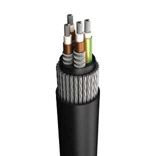
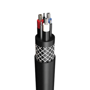
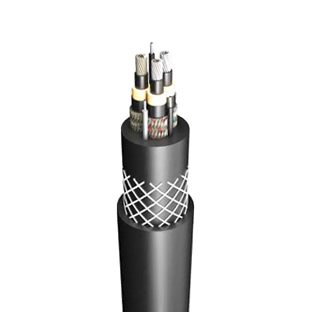
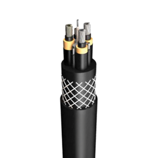
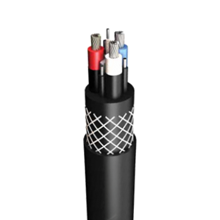
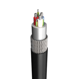
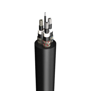
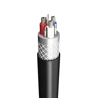
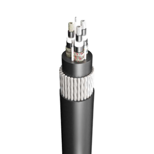
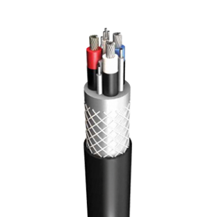
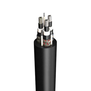
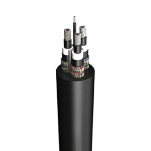
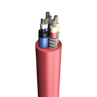
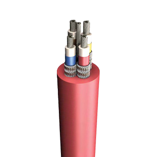
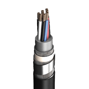
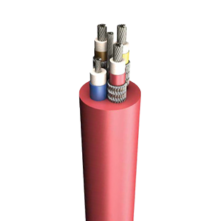
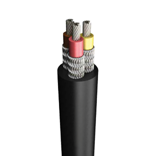
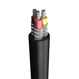
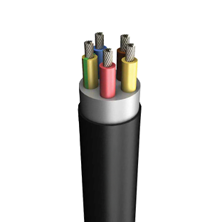
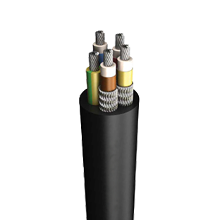
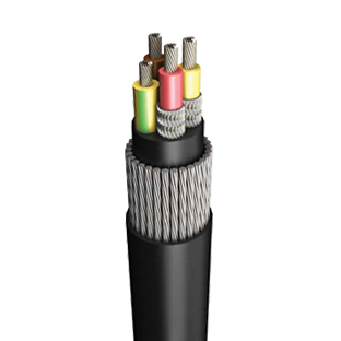
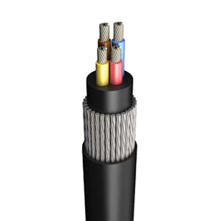
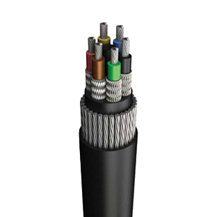
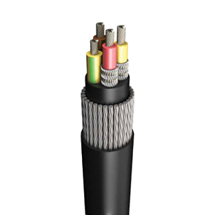
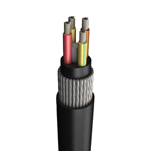
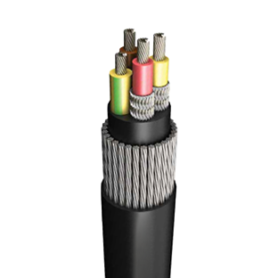
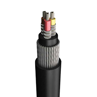
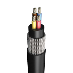
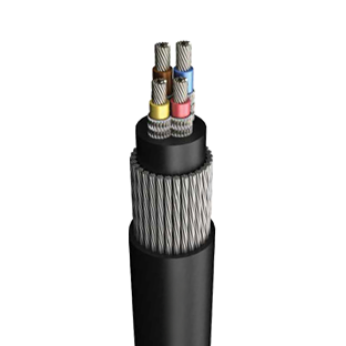
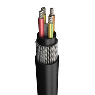
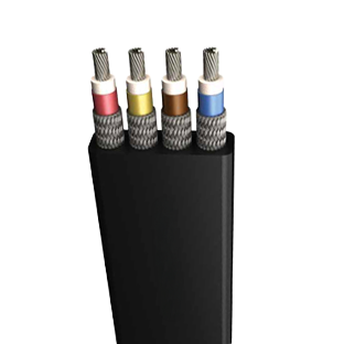
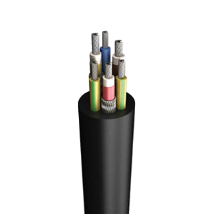
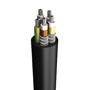
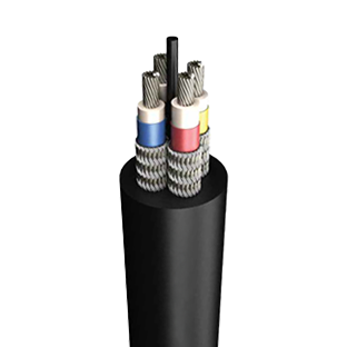
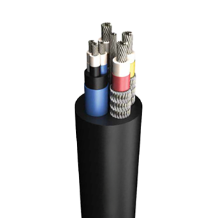
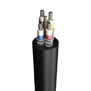
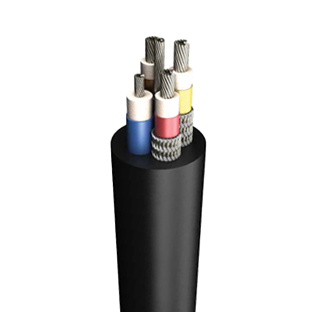
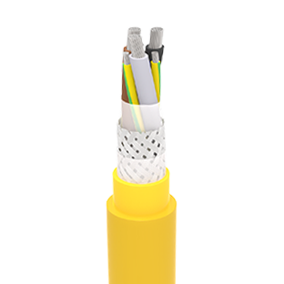
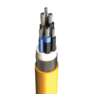
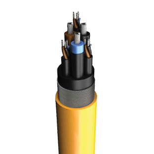
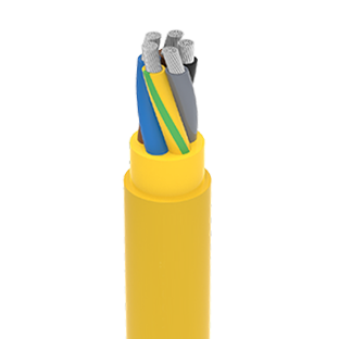
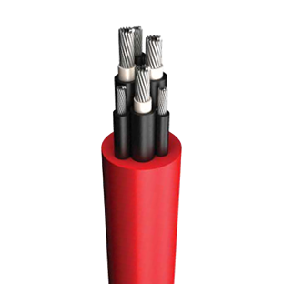
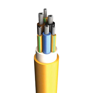
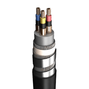
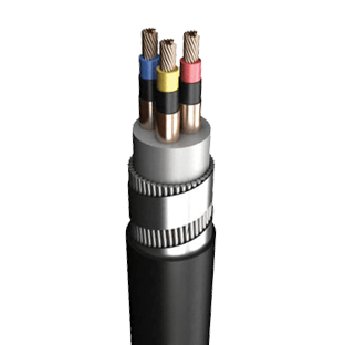
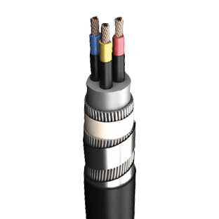
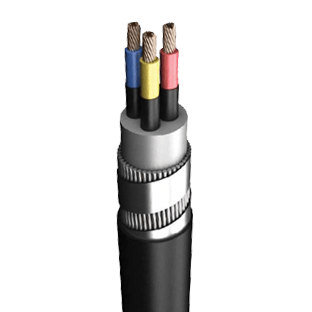
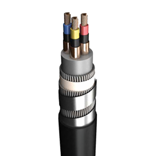
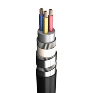
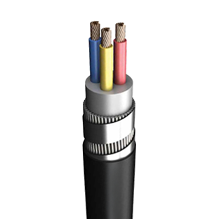
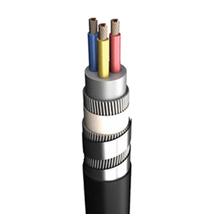
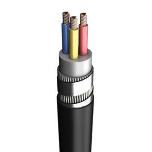
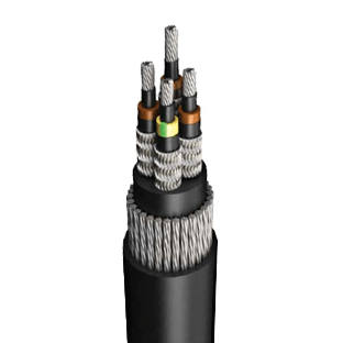
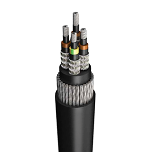
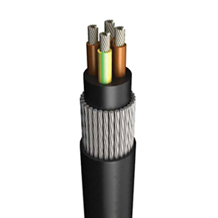
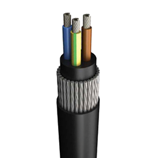
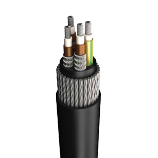
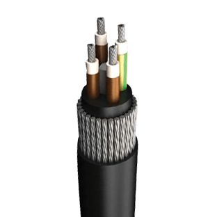
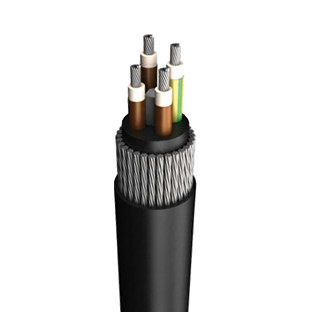
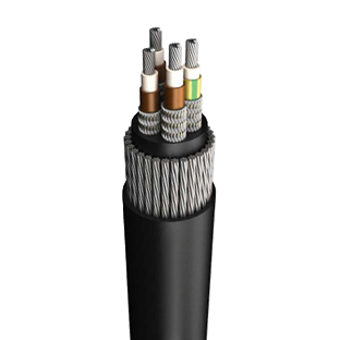
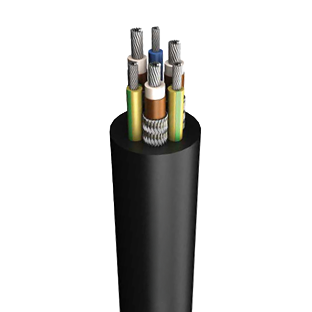
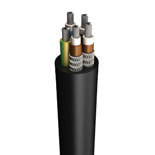
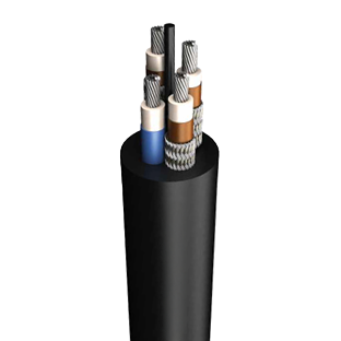
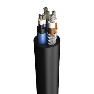
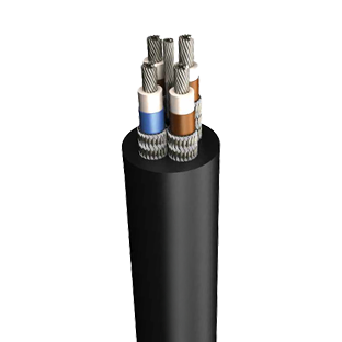
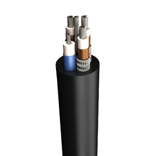
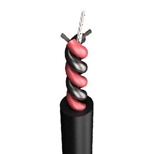
CONDUCTOR : Electrolytic, stranded, tinned copper wire IEC 60228 Class 5
INSULATION : EPR
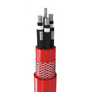
SCREEN : Tinned copper / Nylon braided screen over phase cores. Ground core is not screened on Tip 211.
LAYUP : All cores are laid up in contact with each other.
BEDDING : Rubber based bedding compound.
ARMOUR : Galvanized steel pliable armour.
OUTER SHEATH : Heavy duty chloroprene outer sheath.

RELATED STANDARDS : MGM 112/1984
RATED VOLTAGE : 660/1100 V
TEST VOLTAGE : 3 kV

Conductors3×103×163×253×353×503×703×953×120
MGM 112
Conductors
Conductor diameterNom. mm4.405.507.108.4010.1011.9013.9015.50
Insulation thicknessmm1.51.51.61.61.61.82.02.2
Cable details
Radial thickness of inner sheathmm2.52.52.52.52.52.53.83.8
Min. inner sheath diametermm25.528.732.235.239.544.552.556.6
Max. inner sheath diametermm27.530.734.237.241.547.055.559.6
Size of armourmm7/0,717/0,717/0,717/0,717/0,717/0,907/1,257/1,25
Radial diameter of outer sheathmm3.83.84.14.44.95.45.96.3
Min. overall diametermm37.340.644.648.353.660.771.876.7
Max. overall diametermm39.843.447.451.157.464.575.881.0
Min. bending radiusmm398434474511574645758810
Appx. cable weightkg/km2.523.223.854.65.717.4510.2511.8
Copper weightkg/km4887411.121.8682.493.6864.7666.566
Electrical details
“Continuous current
rating at 25°C Ambient”
A6385110135170205250295
Max. DC resistance at 20°C
Phase conductorsΩ /km1.951.240.7950.5650.3930.2770.2100.164
ArmourΩ /km1.971.761.451.031.000.510.390.30
3 screens in parallel connectionΩ /km1.331.611.101.201.400.700.850.50
Nominal Kesit3×10+103×16+163×25+163×35+253×50+353×70+503×95+703×120+70
MGM 112
Phase Conductors
Number and cross sectionmm23×103×163×253×353×503×703×953×120
Strandingmm80/0,40126/0,40196/0,40276/0,40396/0,40360/0,50475/0,50608/0,50
Conductor diameterNom. mm4.405.507.108.4010.1011.9013.9015.50
Insulation thicknessmm1.51.51.61.61.71.82.02.2
Earth Conductor
Number and cross sectionmm21×101×161×161×251×351×501×701×70
Strandingmm80/0,40126/0,40126/0,40196/0,40276/0,40396/0,40360/0,50360/0,50
Conductor diameterNom. mm4.405.505.507.108.4010.1011.9011.90
Insulation thicknessmm1.51.51.51.61.61.71.81.8
Cable details
Radial thickness of inner sheathmm2.52.52.52.52.53.85.05.0
Min. inner sheath diametermm27.931.635.438.843.751.860.364.9
Max. inner sheath diametermm29.933.637.440.846.254.863.367.9
Size of armourmm7/0,717/0,717/0,717/0,717/0,717/0,907/1,257/1,25
Radial thickness of outer sheathmm3.84.14.44.85.35.86.46.0
Min. overall diametermm39.844.048.552.759.768.880.686.0
Max. overall diametermm42.346.851.356.563.572.884.990.0
Min. bending radiusmm423468513565635728849900
Appx. cable weightkg/km3.053.924.785.87.0810.5516.6519
Copper weightkg/km5848951.1641.6082.1963.0364.0284.758
Electrical details
“Continuous current
rating at 25°C Ambient”
A6385110135170205250295
Max. DC resistance at 20°C
Phase conductorsΩ /km1.951.240.7950.5650.3930.2770.2100.164
Earth conductorΩ /km1.951.241.240.7950.5650.3930.2770.277
ArmourΩ /km1.811.631.451.030.7150.5040.3820.299
3 screens in parallel connectionΩ /km1.331.611.101.201.400.700.850.50


We use cookies on our website to provide you a better experience. For detailed information please visit Our Cookie Policy and Clarification Text.